
Technical Details of Rothberg's New Machine - (i)
Since our readers are interested in learning about cutting-edge technologies, we assembled a team of experts to go over Jonathan Rothberg’s latest imaging/operating instrument mentioned in previous commentary. In a series of blog posts, we will cover the following aspects -
(i) The basic overview of what this device will accomplish,
(ii) Solid state innovations related to combining MEMS/CMUT and CMOS circuitry in the same chip,
(iii) The on-chip waveform generation and receiver/transducer signal- processing aspects,
(iv) 3D volumetric image reconstruction and FPGA-based synchronization between transmitter and receiver,
(v) Potential challenges in developing the technology and making all components work together.
-————————————————————————-
The new instrument is planning to miniaturize and integrate ultrasound imaging and HIFU (High-intensity focused ultrasound) on a silicon chip. We will go over various pieces in the following sections.
1. Traditional ultrasound
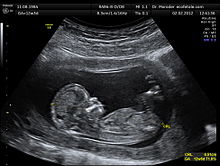
Most readers are familiar with ultrasound imaging of babies. A high-frequency signal is sent inside the body, and various tissues or tissue junctions reflect the signal at variable intensity. Based on received signal, the computer generates a picture of what is inside the body. The process is non- destructive provided the strength of signal sent inside body is low.
Mathematically, how does ultrasound image reconstruction work? This is a high- school level topic in the country where we grew up, and there are excellent websites to go over the details. So, instead of covering the same old topic once again, we provide you with one of the links that also likely explains the name of Rothberg’s new company. In the FFT world, the following circuit is known as butterfly algorithm.
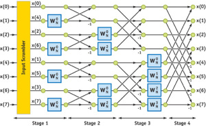
Check Medical Image Reconstruction with the FFT for more details about ultrasound and MRI image reconstructions work.
-——————————————-
**2. HIFU (High-intensity focused ultrasound) **
By increasing the signal strength of ultrasound and focusing on a small area of body, one can also heat up and destroy cells. Believe it or not, this method of frying cells by sending remote signals was first demonstrated in 1942 by two brothers, whose last name was Fry !!
A few details -
How HIFU works
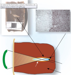
As an acoustic wave propagates through the tissue, part of it is absorbed and converted to heat. With focused beams, a very small focus can be achieved deep in tissues (usually on the order of milimeters, with the beam having a characteristic “cigar” shape in the focal zone, where the beam is longer than it is wide along the transducer axis). Tissue damage occurs as a function of both the temperature to which the tissue is heated and how long the tissue is exposed to this heat level in a metric referred to as “thermal dose”. By focusing at more than one place or by scanning the focus, a volume can be thermally ablated. At high enough acoustic intensities, cavitation (microbubbles forming and interacting with the ultrasound field) can occur. Microbubbles produced in the field oscillate and grow (due to factors including rectified diffusion), and can eventually implode (inertial or transient cavitation). During inertial cavitation, very high temperatures inside the bubbles occur, and the collapse is associated with a shock wave and jets that can mechanically damage tissue. Because the onset of cavitation and the resulting tissue damage can be unpredictable, it has generally been avoided in clinical applications. However, cavitation is currently being investigated as a means to enhance HIFU ablation and for other applications.
High-intensity focused ultrasound in the treatment of solid tumours
Traditionally, surgery has been the only cure for many solid tumours. Technological advances have catalysed a shift from open surgery towards less invasive techniques. Laparoscopic surgery and minimally invasive techniques continue to evolve, but for decades high-intensity focused ultrasound has promised to deliver the ultimate objective truly non-invasive tumour ablation. Only now, however, with recent improvements in imaging, has this objective finally emerged as a real clinical possibility.
High intensity focused ultrasound in clinical tumor ablation
HIFU relies on the same principles as conventional US. The time-averaged intensities of typical diagnostic US (B-mode, pulsed or continuous Doppler) can be up to 720 mW/cm2 according to United States Food and Drug Administration (USFDA) regulations. In contrast, the intensity of HIFU in the focal region is about several orders higher, 100-10?000 W/cm2, with peak compression pressures of up to 70 MPa and peak rarefaction pressures up to 20 MPa.
Two main mechanisms are involved in the HIFU ablation: a thermal effect and a mechanical effect. The thermal effect of HIFU is heat generation due to absorption of the acoustic energy with a rapid elevation of temperature in the local tissue. Tissue temperature elevated to more than 60C for 1 s will generally lead to instantaneous and irreversible cell death via coagulation necrosis in most tissues, which is the primary mechanism for tumor cell destruction in HIFU therapy. Ultrasound beam focusing results in high intensities only at a specific location within a small volume (e.g. about 1 mm in diameter and about 10 mm in length), which minimizes the potential for thermal damage to tissue outside the focal region. Since the thermal mechanism is better understood and its effect is easier to control, it is preferred in tissue ablation.
-——————————————————————-
3. Defects of the current systems (MRgFUS and USgHIFU)
HIFU is a nice distant method for operating inside body without tearing everything apart except for one problem. To operate on a part of the body, one needs to be able to see where he is operating, but in the current methods, the imaging apparatus and the operating instrument are separate. Needless to say, each of them also cost a lot of money. Here is how it is done in the current implementations.
Clinical HIFU procedures are typically performed in conjunction with an imaging procedure to enable treatment planning and targeting before applying a therapeutic or ablative levels of ultrasound energy. When Magnetic resonance imaging (MRI) is used for guidance, the technique is sometimes called Magnetic Resonance-guided Focused Ultrasound, often shortened to MRgFU or MRgHIFU. The procedure is called Magnetic Resonance-guided Focused Ultrasound Surgery or MRgFUS.[1] When diagnostic sonography is used, the technique is sometimes called Ultrasound-guided Focused Ultrasound (USgFUS or USgHIFU).
Currently, MRgHIFU is an approved therapeutic procedure to treat uterine fibroids in Asia, Australia, Canada, Europe, Israel and the United States. USgHIFU is approved for use in Bulgaria, China, Hong Kong, Italy, Japan, Korea, Malaysia, Mexico, Poland, Russia, Romania, Spain and the United Kingdom. Research for other indications is actively underway, including clinical trials evaluating the effectiveness of HIFU for the treatment of cancers of the brain, breast, liver, bone, and prostate. At this time non- image guided HIFU devices are cleared to be on the market in the US, Canada, EU, Australia, and several countries in Asia for the purposes of body sculpting.[2]
-——————————————————————-
4. CMUT and CMUT-in-CMOS
The ultrasonic devices of today use [http://en.wikipedia.org/wiki/Piezoelectricity](<a href=)”>piezoelectric transducers, but recently researchers are proposing a MEMS-based approach called CMUT (Capacitive micromachined ultrasonic transducers). CMUT uses MEMS technology to build transducers on silicon wafers.
Capacitive micromachined ultrasonic transducers (CMUT) is a relatively new concept in the field of ultrasonic transducers. Most of the commercial ultrasonic transducers today are based on piezoelectricity. CMUTs are the transducers where the energy transduction is due to change in capacitance. CMUTs are constructed on silicon using micromachining technique. A cavity is formed in a silicon substrate, and a thin layer suspended on the top of the cavity serves as a membrane on which a metallized layer acts an electrode, together with the silicon substrate which serves as a bottom electrode.
If an AC signal is applied across the biased electrodes, the vibrating membrane will produce ultrasonic waves in the medium of interest. In this way it works as a transmitter. On the other hand, if ultrasonic waves are applied on the membrance of biased CMUT, it will generate alternating signal as the capacitance of the CMUT is varied. In this way, it works as a receiver of ultrasonic waves.[1]
As CMUTs are micromachined devices, it is easier to construct 2D and 3D arrays of transducers using this technology. This means large numbers of CMUTs could be included in a transducer array providing larger bandwidth compared to other transducer technologies. To achieve a high frequency operation using CMUTs is easier due to its smaller dimensions.[2] The frequency of operation depends on the cell size (cavity of membrane), and on the stiffness of the material used as a membrane. As it is built on silicon, the integration of electronics would be easier for the CMUTs compared to other transducer technologies. The properties to use in high frequency with large bandwidth makes it a good choice to use as a transducer in medical imaging, especially in the an intravascular ultrasound (IVUS). Because of its broader bandwidth, it could be used in second-harmonic imaging. Also some experiments have been performed to use CMUTs as hydrophones.
Professor BT Khuri-Yakub’s group in Stanford has expertise in CMUT, and here is a recent paper.
Integrated circuits for volumetric ultrasound imaging with 2-D CMUT arrays
Real-time volumetric ultrasound imaging systems require transmit and receive circuitry to generate ultrasound beams and process received echo signals. The complexity of building such a system is high due to requirement of the front- end electronics needing to be very close to the transducer. A large number of elements also need to be interfaced to the back-end system and image processing of a large dataset could affect the imaging volume rate. In this work, we present a 3-D imaging system using capacitive micromachined ultrasonic transducer (CMUT) technology that addresses many of the challenges in building such a system. We demonstrate two approaches in integrating the transducer and the front-end electronics. The transducer is a 5-MHz CMUT array with an 8 mm 8 mm aperture size. The aperture consists of 1024 elements (32 32) with an element pitch of 250 ?m. An integrated circuit (IC) consists of a transmit beamformer and receive circuitry to improve the noise performance of the overall system. The assembly was interfaced with an FPGA and a back-end system (comprising of a data acquisition system and PC). The FPGA provided the digital I/O signals for the IC and the back-end system was used to process the received RF echo data (from the IC) and reconstruct the volume image using a phased array imaging approach. Imaging experiments were performed using wire and spring targets, a ventricle model and a human prostrate. Real-time volumetric images were captured at 5 volumes per second and are presented in this paper.
-——————————————————-
5. What is new?
There are two novel aspects of Rothberg’s proposed technology -
(i) Rothberg’s company is developing a technology to combine CMUT (MEMS technology) and traditional CMOS circuitry on the same chip. That way, they will be able to rapidly process large amount of signal received by the transducer array on chip. This will help in real-time 3D reconstruction of the images.
(ii) With this improvement, they are also proposing to combine ultrasound imaging and HIFU operating using the same device. The device will have dual mode of operation. It can be used as a scanner and by flipping a switch, the signal strength can be increased to operate on a selected tissue (such as a tumor).
We will cover each topic in detail in the following blog posts. In the next post, we will discuss the details of the low temperature ( <450C ) IC metallization layer processing method to combine CMUT and CMOS.