
Designing a Traffic Signal Light
We have updated the previous commentary on GPU and FPGA with few references and will continue to add more. In this follow-up post on GPU and FPGA series, we will present a very simple electronics problem - design of a traffic signal light. It will be used as a model to elaborate on various concepts in future sections.
We picked traffic signal lights, because they are ubiquitously present all over the world, or at least the part of the world that accesses our blog. Therefore, there should not be any confusion about what they do. How do they keep changing from red–>green–>yellow–>red all day and night? We will show the design of a simple electronic circuit to control one set of traffic signals. The same concept can be extended to build more complex cases, such as inclusion of a left-turn, or timed walk signal, or synchronized signals at different sides of a five way intersection. In fact, designs of the most complex microprocessors and other logic circuits use very similar hardware design concepts.
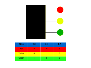
Above is a cartoon picture to describe our design. The black box, which contains electronic circuitry, will control three signal lights. When the output on a wire is 1 or high voltage, the corresponding light is on. When the output is 0 or low voltage, the light is off. The timing diagram of three wires is shown in the table. From time 0-2, the green will be on and other lights will be off. From time, 3-4, yellow will be on and others off. Then red stays on from time 5-7. Time is measured modulo 8. Therefore, red will be followed by green from time 8-10 and so on.
To build the black box, we will need a set of Lego blocks, and the following pieces are used.
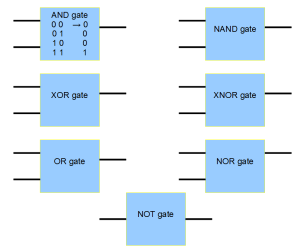
Each of the box in the picture is a logic gate. Left side of the box shows the input(s) and right side shows the output.
When the inputs to a box turn to high (1) or low (0), the output immediately adjusts. As an example, we have described the function of the AND block. When both of its inputs change to high, the output is high. If one or other input change to low, output turns low. The functions of remaining logic gates are described at this link. Those logic gates are sold as discrete parts at all electronics store. They look like this -

Are you familiar with the above picture? Not unless you open the back of your laptop or PC, and look inside.
The Lego pieces presented above are known as ‘combinatorial logic’. For them, the output changes immediately with adjustment of input. To build signal light, we will need another piece called ‘sequential logic’.
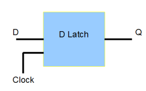
The piece above is known as D flip-flop, and it operates in the following manner. When the ‘clock’ signal is low, the output stays as it is, irrespective of change in input. When the ‘clock’ turns high, input is carried into output. Therefore, the logic circuit has a memory. In fact, DRAM memories in all of our computers are built with millions or billions of such D latches.
Can you think of how to build the signal light controller with the above Lego pieces? The answer will follow in the next commentary.
Two quick points -
(i) Although we said that the outputs of combinatorial logic gates changed immediately with change in input, that is not correct. Nature imposes limits on any electronic circuit by creating very small delay between input and output. Do not use that argument, when you get caught after jumping a red light, because the delay is in picoseconds to nanoseconds.
(ii) There is a message for biologists trying to figure the operation of complex genetic circuits. All seven combinatorial gates and the sequential gate in the above pictures can be built with exactly one gate (NAND or NOR). Every complex circuit in every large computer is built with one gate and complexity arises from the wiring. In the same vein, it is not necessary for more complex organisms to have more number of genes, because the complexity can be derived by changing the connections between genes. Oh well, in how many ways do we have to prove ENCODE wrong before people come to their senses? In fact, in 2006, we were proceeding with the above rationale to understand the new functional toolkits of the genome, when ENCODE and cancer yahoos jumped in and destroyed the whole field.